Part 1:
- At each test point the values are 1023, 614, 409, 204. The analog to digital converter on an Arduino is 10 bits, the highest acceptable voltage is 5V, so to register the analog voltage as a digital value, it assigns it a value between 0 and 1023.
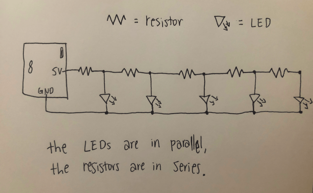
- Ohm’s law is V= I*R, and we are looking for the expected voltage at each test point. So I is current and R is resistance. At test point 1, the resistance is 220 ohms, and the 5V pin outputs 40mA or 0.04A. So 220*0.04 = 8.8V At test point 2, the resistance is 440 ohms, so 440*0.04 = 16.7V. At test point 3, the resistance is 660 ohms, so 660*0.04 = 26.4V. At test point 4, the resistance is 880 ohms 880*0.04 = 35.2V.
- The code that displays the voltage in the serial monitor is below.
float value = 0.0;

void setup() {
  Serial.begin(9600);
}

void loop() {
  int analogValue = analogRead(A0);
  value = (analogValue * 5.0) / 1024.0;
  Serial.print("voltage = ");
  Serial.println(value);
  delay(100);
}
Part 2:
- Each LED was at a lower voltage after each resistor. The LEDs get dimmer as the circuit continues, given that each resistor in series drops the voltage provided to the LEDs.
2+3 are below!

Leave a comment