For this assignment, I chose my laptop because it is incredibly important to me, especially with all of my classes being remote. I wanted to make something meaningful to me, but also simple, and something that would be understood by most people as a laptop. I want to keep working toward understanding Cinema 4D more, as I think something I am confused about is cameras vs render, and what actually sends the information out of Cinema 4D into After Effects.
-
After following the above tutorial, I made a little character that blinks. I was trying to find a better tutorial that more suited the projected time of an hour rather than 3-4 hours, and this was at a lower end of the spectrum, and didn’t take me nearly as long as expected. I still enjoyed it, however. I like working with the onion skins. I also really enjoy hand drawn animations. I love rotoscoping too, just something feels different about coming up with it yourself. Had a lot of fun with this.

-
I used my Glitch assignment from Image as the base for this project. Unfortunately I was unable to get one layer to load properly. I wanted to use this assignment because I thought that taking all the layers from their original positions and rotating them to be in the correct position would be a cool effect. I think it turned out to be creepier than expected. I picked this piece because it was interesting to work on, and one of the best options I had for old .psd files. It uses characters from the Haunting of Hill House TV show, along with myself.
-
I followed the above tutorial. This was a 20 minute tutorial, but it took me much longer than 20 minutes to complete this. I did not plan on it taking so much time but it was fun. I really enjoy the final product as well, especially because this is my first time animating something on my own, without rotoscoping.
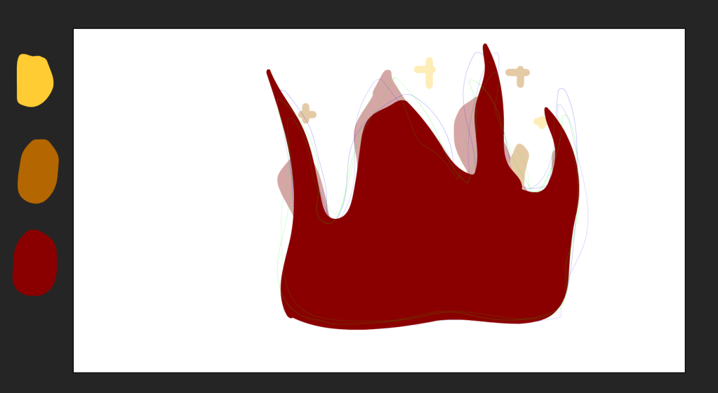
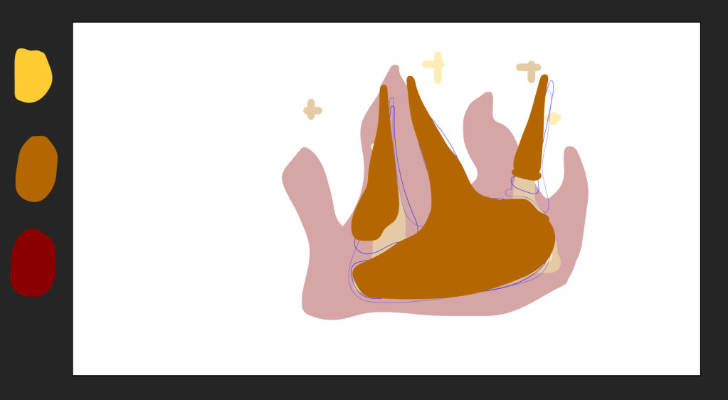
Below are the progress shots, in which I had to do each color animated.

-
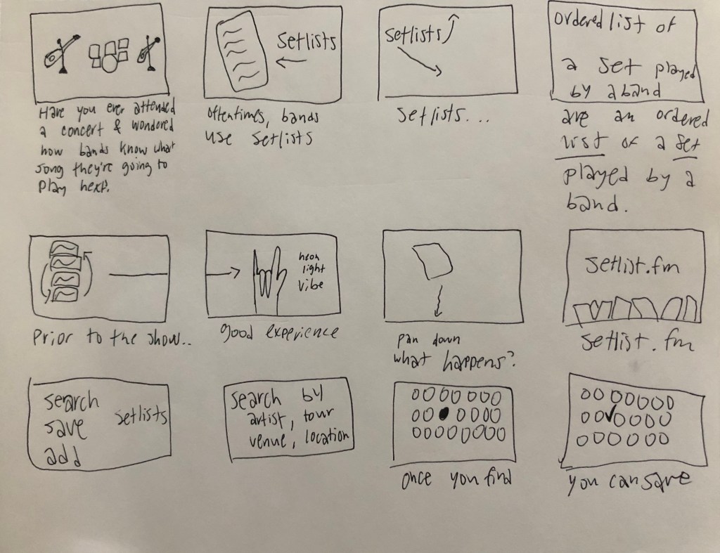
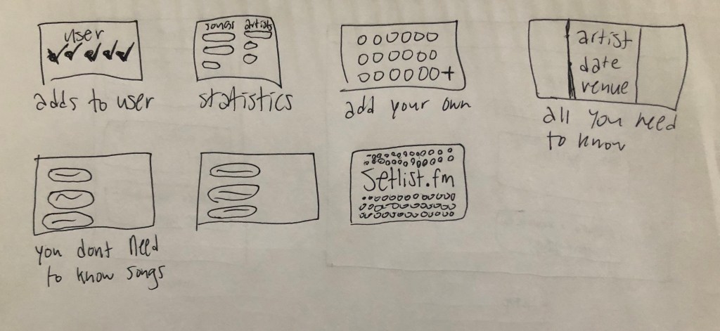
Revised and redid some things, but had a lot of fun with this one, love setlist.fm and enjoyed the creation of the video.
-
Formal Summary of Project
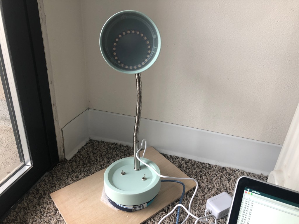
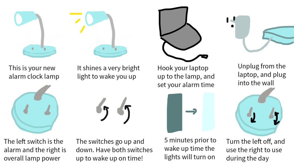
For my final project in Object, I built a lamp thats main purpose is to wake someone up. Instead of a standard audio alarm, this is intended to simulate the sun rising, but can be programmed to wake you up at a specific time. The purpose is to make waking up not as startling and sudden, but easing someone into lightness.For my physical components, I used a desk lamp, an arduino uno, a real time clock DS3231, two toggle switches, a 9V DC converter, a neopixel 24 ring (it can be a different size if wanted), jumper wires, a transistor, and a small breadboard. Once you have all of these items, you can begin working. My code is below, including the example code that could be found elsewhere, but was included for ease.
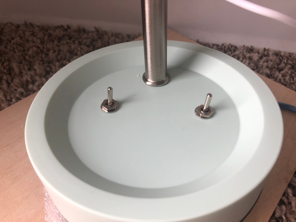
The body of the lamp is from a standard target desk lamp. The desk lamp was removed of its lights and wires, so it was only the head, the stand, and the neck (bendy metal part that connects the stand and head.) This is set aside and used later. The neopixel must be tested by connecting it to ground, 5v, and data in, with test code from adafruit neopixel simple, under examples in the arduino desktop app. Once you are sure the neopixel is working, it is time to figure out the real time clock. The real time clock (RTC) should have a battery. If it doesn’t, you need to buy one. Connect the RTC to the arduino, using jumper wires, connect the SCL on the RTC to the SCL port on the arduino. SDA on the RTC should be connected to the SDA port on the arduino. The VCC on the RTC should be connected to 5V on the arduino, and GND on the RTC to ground on the arduino. This needs to be set using DS3231_set in the DS3231 examples in the arduino desktop app. Open the serial monitor and make sure that the time matches up with your clock on your computer. The battery needs to be in, and the wires need to be hooked up. If for some reason the RTC ever changes from the time you previously set it to, just repeat this step, and it will go back to the right time.
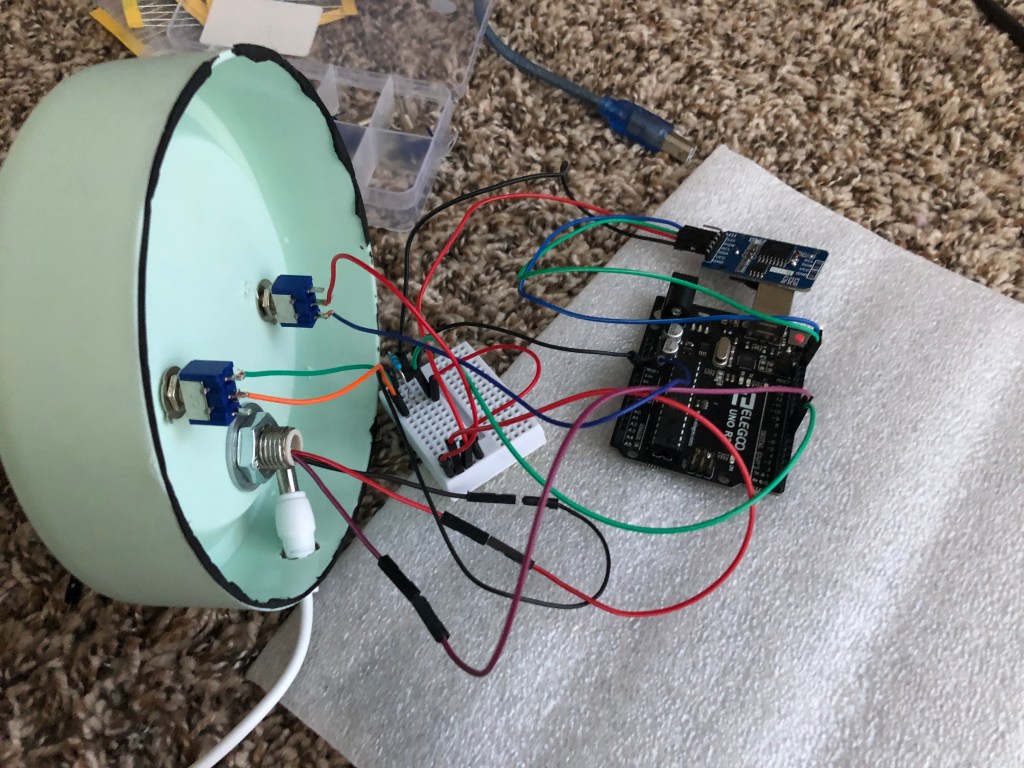
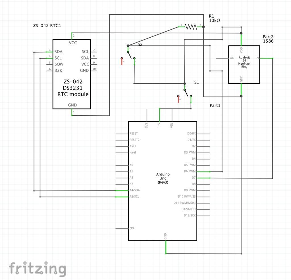
Because both are working, it is time to put everything together. This can all be seen in the digitally drawn schematic below. Ensure you do not plug in the arduino until needed. The toggle switches need to be attached to wires, be it solder or trickily wrapping wire around the bottom, like I did. There only needs to be two wires, one in the middle of the toggle switch and one on the outside. There is no need for 3 wires. On toggle switch 1, the outside wire needs to go into the 5v on the arduino uno board. The middle wire toggle switch 1 needs to go into the far left column (column 1) of your small breadboard. From there, the neopixel’s 5v wire needs to be in column 1, same as the middle wire of toggle switch 1. The real time clock’s VCC needs to be connected to column 1 as well. Finalizing this column, use a jumper wire to connect column 1 to column 10. Put the middle wire of toggle switch 2 into column 10, and the outside wire to column 11. Put a 10k resistor connecting column 11 and the last column (column 15). Put a jumper wire from column 11 to port 6 on the arduino board. Column 15 is the grounding column, so connect the ground of both the neopixel and the RTC to column 15 with jumper wires. Connect column 15 to the ground port on the arduino board. Connect the “in” hole on the neopixel to port 7 on the arduino board. Then use the code, upload it to the arduino board, and you should be set.
Overall, the RTC keeps track of the real time, sends it to the arduino, the arduino checks the code that was last uploaded and compares the RTC to the number inputted for the alarm time. Five minutes before the alarm time, the neopixel begins to light up (controlled by pin 7), going from 1 to 255 by the time the alarm was set. One toggle switch controls if the alarm light is on or off, the other controls if the entire lamp is on or off. After a certain point, the lamp can be turned on for use as a normal lamp.
Digitally Drawn Schematic
Graphics and Interaction Diagrams
Finished Project Photos
Demo Video
-
Here is my creative brief, linked, or below as a pdf.
My outline:
- What setlists are
- Why the website is valuable
- How to use the website
- Finding other setlists
- Adding them to your previous concerts
- Adding to setlists
- Creating new setlists
-
What did I accomplish this week?
- Began working with the neopixel and got half of it to light up
- Figured out the battery for the real time clock was not there and switched the battery from the remote into the real time clock
What do I need to have done to have a MVP (minimal viable product)?
- Get the full neopixel to work and be bright in the lamp
- Have the neopixel connect to the real time clock and begin to turn on at a certain time
- Have the neopixel also turn on when needed for a normal lamp
What do you have documented already?
- I have the LCD screen working (after many wires and a few tries), and the neopixel half working…and by half working I mean 12 of the 24 lights are lighting up. Strange.